
By the end of this chapter, you will be able to:
Mastering these skills will help you communicate your welding work clearly and professionally, making sure every job is done right the first time!
Draft working drawings are essential in Metal Inert Gas (MIG) welding as they provide a precise visual representation of the components to be fabricated or assembled. In Kenya’s diverse professional sectors such as bottling plants, printing works, hotel kitchens, and farm packing sheds, accurate interpretation of these drawings ensures that welding projects meet design specifications and quality standards. This chapter focuses on the fundamental skills required to read, understand, and produce draft working drawings, enabling diploma-level students to apply MIG welding techniques effectively across various industries.
Drawing interpretation is the skill of reading a technical drawing so that the part can be made correctly before any cutting or welding starts. It covers dimensions, tolerances, symbols, views, scale, and angles, and the ability to sketch plane shapes and solids to explain or check a design. Reading the drawing correctly avoids wrong cuts, poor fit-up, and rework in the welding workshop.
Dimensions on a drawing give the exact size and position of each feature of the workpiece. Correct reading of dimensions makes sure that the welded parts fit together as intended. Example: a welding workshop making a steel frame reads the length of each bar and the position of each hole from the drawing before it marks out the metal.
Linear dimensions give length, width, height, thickness, and distance between features, using a straight dimension line with a numerical value. Unless the drawing states otherwise, the values are in millimetres. Example: a drawing of a 5 mm flat bar shows its length as 450, which means 450 mm.
Angular dimensions give the angle between two lines or surfaces, in degrees. They are used for bevels, mitres, and bent parts. Example: a drawing of a plate edge for welding may show a bevel angle of 30°, which the welder prepares by grinding.
Dimensions are read from the dimension lines, extension lines, and numbers together.
A technical drawing illustrating the use of extension lines and dimens (Source: 59d646f026634d9a)
A tolerance is the permitted variation in a dimension. No part can be made to an exact size, so the tolerance sets the upper and lower limits within which the part still fits and works. Example: a hole in a bracket given as 12 ± 0.2 mm may be anything from 11.8 to 12.2 mm.
Worked example: a bar is dimensioned 120 ± 0.5 mm.
Formula: upper limit = nominal + tolerance, and lower limit = nominal − tolerance
Substitution: upper = 120 + 0.5, and lower = 120 − 0.5
Working: 120.5 and 119.5
Result: the bar is acceptable if its length is between 119.5 mm and 120.5 mm, and the total tolerance is 1.0 mm.
Symbols and notations give short, standard information on the drawing about weld type, joint, and finish. They save space and avoid long written instructions. Example: a fillet weld symbol with a size beside it tells the welder the type and the leg length of the weld at the joint.
Views, or elevations, show the object as seen from different directions, so that the whole shape can be understood and made. One view alone seldom shows all the features of a welded part. Example: a welded stand may need a front view for its height, a top view for the base plate, and a side view for the position of the braces.
In first angle projection the object is placed in the first quadrant, between the viewer and the projection plane. The front view is drawn first, the view from above is placed below the front view, and the view from the left is placed on the right of the front view. The symbol for first angle shows a truncated cone with the circular end on the right. Example: a drawing of a steel bracket in first angle puts its plan under its front view.
In third angle projection the projection plane is placed between the viewer and the object. Each view is drawn on the side nearest to where it is seen, so the view from above is placed above the front view, and the view from the right is on the right. The symbol for third angle shows a truncated cone with the circular end on the left. Example: the same bracket drawn in third angle puts its plan above its front view.
A 3D isometric view of a stepped block (Source: 697c72e40165f702)
Scale is the ratio between the size of the drawing and the actual size of the object. It allows a large object to fit on a sheet of paper, and a small part to be drawn large enough to show its detail. Example: a welding workshop draws a large frame at 1:10 and a small bracket at 2:1.
Worked example: a length measures 40 mm on a drawing at scale 1:5.
Formula: actual size = drawing size × scale factor
Substitution: actual = 40 × 5
Working: 40 × 5 = 200
Result: the actual length is 200 mm.
Angles are measured to prepare joints and to set parts in position for welding. They are measured on drawings and on the workpiece with simple instruments. Example: a welder checks the 60° included angle of a plate preparation with a bevel gauge and protractor before welding.
| Name | Specification | Use |
|---|---|---|
| Protractor | Graduated in degrees, 0° to 180° | Measuring and marking angles on drawings |
| Bevel gauge | Adjustable blade with a lock | Transferring and setting angles |
| Combination square | Includes a protractor head | Measuring angles and checking squareness |
| Digital angle finder | Electronic display | Precise angle measurement |
| Try square | Fixed 90° | Checking right angles |
Care: check the instruments before use, hold them firmly against the edges, and align the zero mark correctly.
Sketching plane shapes lets the welder show the layout of a part before a full drawing is made. A sketch is made quickly by hand, with light guidelines first and firm outlines after. Example: a welder sketches a triangular gusset on a plate, with its dimensions, to agree its size with the supervisor.
A triangle has three sides and three angles that add up to 180°. Triangles are used in gussets and bracing. Example: a triangular gusset joins a post to a base plate.
A quadrilateral has four sides, and its angles add up to 360°. Plates, frames, and panels are quadrilaterals. Example: a rectangular base plate has four right angles and opposite sides equal.
A polygon is a closed shape with straight sides, and a regular polygon has equal sides and equal angles. Hexagonal and octagonal shapes occur in nuts and in plate profiles. Example: a hexagon of side 30 mm is marked out for a base plate.
Worked example: the interior angle of a regular hexagon.
Formula: interior angle = (n − 2) × 180° ÷ n
Substitution: (6 − 2) × 180° ÷ 6
Working: 4 × 180 ÷ 6 = 120
Result: each interior angle is 120°.
A circle is the set of points at a fixed distance, the radius, from the centre. A tangent is a straight line that touches the circle at one point and is at right angles to the radius at that point. Tangents are used where a straight edge runs smoothly into a curve, for example in a bent bar. Example: a flat bar bent round a pipe of radius 50 mm leaves the bend along a tangent.
Solid sketches show three-dimensional objects, so that the welder can see the spatial relationship of the parts. They are made with isometric or oblique lines, starting from the base shape. Example: a welding workshop sketches a cylindrical tank on a rectangular stand before making a detailed drawing.
A prism has two equal parallel ends, and its sides are flat faces. The cross-section is the same along its length. Beams and structural members are prisms. Example: a triangular prism is a roof-shaped support.
A cone has a circular base and a curved surface that tapers to a point, the apex. Hoppers and funnels have conical shapes. Example: a hopper for grain has a cone at the bottom.
A cube has six equal square faces and twelve equal edges. It is the simplest solid to sketch. Example: a cubic box frame with edges of 300 mm is made from welded bar.
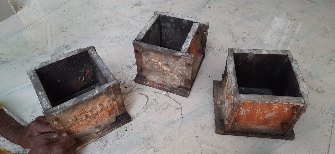
Concrete cube molds for testing (Source: Wikimedia Commons)
A cuboid has six rectangular faces, and its length, width, and height may all be different. Tanks, boxes, and plates are cuboids. Example: a rectangular steel tank is a cuboid.
A cylinder has two equal circular ends joined by a curved surface. Pipes, tanks, and drums are cylinders. Example: a pipe or a storage tank has a cylindrical shape.
Worked example: the volume of a cylindrical tank of radius 50 mm and height 300 mm.
Formula: V = π × r² × h
Substitution: V = 3.142 × 50² × 300
Working: 3.142 × 2500 × 300 = 2,356,500
Result: the volume is 2,356,500 mm³, which is about 2.36 litres.
Explain the importance of tolerances in MIG welding and describe the different types commonly used. (10 marks)
Given a drawing with a scale of 1:5, a length measured on the drawing is 40 mm. Calculate the actual length of the object. Show your working. (5 marks)
Identify and describe four common welding symbols used on technical drawings. (8 marks)
Describe the procedure for measuring an angle on a drawing using a protractor. (7 marks)
Sketch and label a rectangular plate with a circular hole at its center, indicating all relevant dimensions, including tolerances. (10 marks)
Create a free account to open more of this chapter.
Free: practical guides, quick cards, workplace scenarios and more.
Create a free accountThis chapter covers the essential aspects of draft working drawings relevant to metal inert gas welding. It begins with drawing interpretation, focusing on understanding linear and angular dimensions, the application of tolerances, and the use of standard symbols and notations. The chapter explains the different views and elevations, specifically the first angle and third angle projections, and discusses the importance of scale and accurate measurement of angles. It then guides the sketching of plane geometric forms such as triangles, quadrilaterals, polygons, circles, and tangents, followed by the sketching of solid shapes including prisms, cones, cubes, cuboids, and cylinders. Moving on to draft work drawings, the chapter highlights the significance of proper drawing dimensions and the correct use of welding symbols and notations. Finally, the operation procedure section outlines the development of the drawings and their practical use in the welding process, ensuring clear communication and precise fabrication.
Type: Individual
| Tools & Equipment | Materials |
|---|---|
| Scriber | Mild steel plate 150 × 100 × 6 mm |
| Steel rule | Technical drawing sheet with welding symbols |
| Try square | |
| Welding helmet | |
| Leather gloves | |
| Safety boots | |
| Leather apron |
| S/N | Item | Quantity |
|---|---|---|
| 1 | Technical drawing sheet with welding symbols | 1 per Candidate |
| 2 | Mild steel plate 150 × 100 × 6 mm | 2 pieces per Candidate |
| 3 | Metal Inert Gas (MIG) welding machine with accessories | 1 set per 2 Candidates |
| 4 | Scriber | 1 per Candidate |
| 5 | Steel rule | 1 per Candidate |
| 6 | Try square | 1 per Candidate |
| 7 | Welding helmet | 1 per Candidate |
| 8 | Leather gloves | 1 pair per Candidate |
| 9 | Safety boots | 1 pair per Candidate |
| 10 | Leather apron | 1 per Candidate |
| Items to be Evaluated | Marks Available | Marks Obtained | Comments |
|---|---|---|---|
| TASK 1: Adherence to Safety Procedures | |||
| Wore welding helmet (Award 1 or 0 mark) | 1 | ||
| Wore safety boots (Award 1 or 0 mark) | 1 | ||
| Wore leather gloves (Award 1 or 0 mark) | 1 | ||
| Wore leather apron (Award 1 or 0 mark) | 1 | ||
| Sub-Total | 4 | ||
| TASK 2: Interpretation of Technical Drawing | |||
| Correctly identified all welding symbols on the drawing (Award 3 or 0 marks) | 3 | ||
| Correctly interpreted joint types (butt, fillet, lap) as per drawing (Award 3 or 0 marks) | 3 | ||
| Identified all dimensional specifications including plate size and weld sizes (Award 4 or 0 marks) | 4 | ||
| Sub-Total | 10 | ||
| TASK 3: Identification of Welding Parameters | |||
| Specified appropriate welding current and voltage settings for 6 mm plate (Award 3 or 0 marks) | 3 | ||
| Identified correct gas flow rate for MIG welding (Award 2 or 0 marks) | 2 | ||
| Recognized electrode wire type and diameter as per drawing notes (Award 3 or 0 marks) | 3 | ||
| Sub-Total | 8 | ||
| TASK 4: Safety and Equipment Setup Verification | |||
| Verified welding machine was switched off before setup (Award 1 or 0 mark) | 1 | ||
| Checked that welding cables were connected firmly (Award 1 or 0 mark) | 1 | ||
| Confirmed gas cylinder valve was closed after inspection (Award 1 or 0 mark) | 1 | ||
| Sub-Total | 3 | ||
| TASK 5: Housekeeping | |||
| Left work area clean and tidy (Award 2 or 0 marks) | 2 | ||
| Disposed of waste materials appropriately (Award 2 or 0 marks) | 2 | ||
| Returned tools and materials to designated storage (Award 2 or 0 marks) | 2 | ||
| Sub-Total | 6 | ||
| PRODUCT CHECKLIST | |||
| Accurately identified all welding symbols and notations as per the technical drawing (Award 10 or 0 marks) | 10 | ||
| Correctly interpreted all joint types and welding specifications (Award 10 or 0 marks) | 10 | ||
| Precisely identified all required welding parameters including current, voltage, wire type, and gas flow (Award 11 or 0 marks) | 11 | ||
| Demonstrated understanding of dimensional specifications matching 150 mm x 100 mm x 6 mm plates (Award 9 or 0 marks) | 9 | ||
| Sub-Total | 40 | ||
| GRAND TOTAL | 71 | ||
Type: Individual
| Tools & Equipment | Materials |
|---|---|
| Steel rule | Mild steel plate 300 mm x 200 mm x 5 mm |
| Scriber | |
| Try square | |
| Engineer’s square | |
| Divider | |
| Dot punch | |
| Ballpein hammer | |
| Angle gauge | |
| Leather gloves | |
| Leather apron | |
| Overall | |
| Safety boots |
| S/N | Item | Quantity |
|---|---|---|
| 1 | Mild steel plate 300 mm x 200 mm x 5 mm | 1 Pc per Candidate |
| 2 | Steel rule | 1 Pc per Candidate |
| 3 | Scriber | 1 Pc per Candidate |
| 4 | Try square | 1 Pc per Candidate |
| 5 | Engineer’s square | 1 Pc per Candidate |
| 6 | Divider | 1 Pc per Candidate |
| 7 | Dot punch | 1 Pc per Candidate |
| 8 | Ballpein hammer | 1 Pc per Candidate |
| 9 | Angle gauge | 1 Pc per Candidate |
| 10 | Leather gloves | 1 Pair per Candidate |
| 11 | Leather apron | 1 Pc per Candidate |
| 12 | Overall | 1 Pc per Candidate |
| 13 | Safety boots | 1 Pair per Candidate |
| Items to be Evaluated | Marks Available | Marks Obtained | Comments |
|---|---|---|---|
| TASK 1: Adherence to safety procedures | |||
| Wore overall (Award 1 or 0 mark) | 1 | ||
| Wore leather gloves (Award 1 or 0 mark) | 1 | ||
| Wore leather apron (Award 1 or 0 mark) | 1 | ||
| Wore safety boots (Award 1 or 0 mark) | 1 | ||
| Sub-Total | 4 | ||
| TASK 2: Preparation and marking | |||
| Selected correct mild steel plate (Award 1 or 0 mark) | 1 | ||
| Used steel rule and scriber correctly for linear measurements (Award 2 or 0 marks) | 2 | ||
| Used try square and engineer’s square to mark right angles (Award 2 or 0 marks) | 2 | ||
| Used angle gauge to mark 60° accurately (Award 2 or 0 marks) | 2 | ||
| Used divider and dot punch to scribe reference points (Award 1 or 0 mark) | 1 | ||
| Used ballpein hammer to make clear punch marks (Award 1 or 0 mark) | 1 | ||
| Sub-Total | 9 | ||
| TASK 3: Housekeeping | |||
| Left work area clean and safe (Award 1 or 0 mark) | 1 | ||
| Disposed waste as per workplace procedure (Award 1 or 0 mark) | 1 | ||
| Returned tools and unused materials to store (Award 1 or 0 mark) | 1 | ||
| Sub-Total | 3 | ||
| PRODUCT CHECKLIST | |||
| Linear dimensions marked at 250 mm ±1 mm and 150 mm ±1 mm (Award 5 or 0 marks) | 5 | ||
| Angular dimension marked at 60° ±1° (Award 5 or 0 marks) | 5 | ||
| Lines are straight, clear, and accurately scribed (Award 4 or 0 marks) | 4 | ||
| Punch marks are clear and correctly positioned (Award 4 or 0 marks) | 4 | ||
| Sub-Total | 18 | ||
| GRAND TOTAL | 34 | ||
At the start of this chapter we promised you would be able to:
Tick each one you can genuinely do.
So, are you there yet?
You're competent when you can confidently do 50% or more of what this chapter promised.
Sign in to record how you're doing.