
Orthographic drawings are fundamental in plumbing design and installation, providing precise, multi-view representations of plumbing systems that ensure accuracy and clarity. For plumbing professionals in Kenya, mastery of orthographic projection facilitates effective communication with engineers, architects, and contractors, reducing costly errors on site. This chapter explores essential terms and concepts underpinning orthographic drawings, as well as the standardized symbols and abbreviations specific to plumbing, enabling technicians to produce and interpret drawings that comply with Kenyan and international standards.
Orthographic drawings rely on a set of technical terms and concepts that define how three-dimensional plumbing components are represented in two-dimensional views. Understanding these terms is crucial for plumbing professionals to accurately interpret design intent and execute installations according to specifications, especially within Kenya’s construction industry where compliance with standards is mandatory.
Orthographic projection is a method of representing a three-dimensional object in two dimensions by projecting its features onto multiple planes.
Side View: Complements the front and top views by showing depth and hidden details.
Importance: In plumbing, these views ensure that pipe sizes, slopes, and connection points are clearly communicated.
Scale and dimensioning are key concepts in orthographic drawings that allow large plumbing systems to be represented on manageable paper sizes without loss of proportional accuracy.
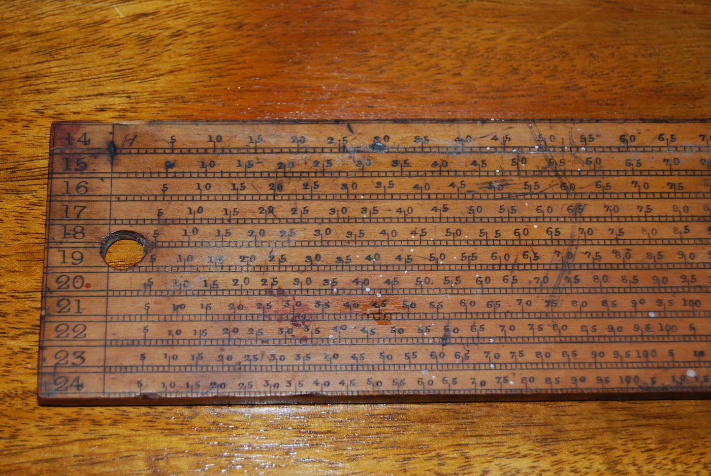
Wooden architect's scale ruler with measurement markings (Source: Wikipedia (Scale ruler))
Lines in orthographic drawings convey different information depending on their style, thickness, and pattern, which is standardized to maintain clarity.
Sectional views are cross-sectional representations of plumbing components or systems, revealing internal features hidden in orthographic views.
Create a free account to open more of this chapter.
Free: practical guides, quick cards, workplace scenarios and more.
Create a free accountThis chapter introduced key terms and concepts fundamental to producing accurate orthographic drawings, providing a foundation for understanding technical representation. It detailed the common symbols and abbreviations used in technical drawings to ensure clarity and standardization. The distinctions between first and third angle projection methods were explained, highlighting their application in orthographic drawing layouts. Orthographic elevations were explored with emphasis on proper dimensioning techniques to convey precise measurements, and methods for converting orthographic views into pictorial representations were demonstrated. The chapter also covered isometric drawings, describing how to represent three-dimensional objects on two-dimensional surfaces while maintaining scale. Oblique drawings were examined as an alternative pictorial technique, focusing on their construction and visual impact. Finally, freehand sketching was discussed as an essential skill for quick, informal communication of design ideas and concepts in technical drawing practice.
Type: Individual
| Tools & Equipment | Materials |
|---|---|
| Mechanical pencil 0.5mm | Technical drawing template paper A3 size |
| Eraser | Tracing paper |
| Set square 45° and 60° | Drawing symbols and abbreviations reference chart |
| T-square | |
| Scale ruler (metric) |
| S/N | Item | Quantity |
|---|---|---|
| 1 | Technical drawing template paper A3 size | 1 Sheet per Candidate |
| 2 | Mechanical pencil 0.5mm | 1 Pc per Candidate |
| 3 | Eraser | 1 Pc per Candidate |
| 4 | Set square 45° and 60° | 1 Set per Candidate |
| 5 | T-square | 1 Pc per Candidate |
| 6 | Scale ruler (metric) | 1 Pc per Candidate |
| 7 | Drawing symbols and abbreviations reference chart | 1 Chart per Candidate |
| 8 | Tracing paper | 1 Sheet per Candidate |
| Items to be Evaluated | Marks Available | Marks Obtained | Comments |
|---|---|---|---|
| TASK 1: Use of PPE and workspace preparation | |||
| Wearing appropriate PPE (dustcoat, safety boots, eye protection) (Award 1 mark for correct PPE worn or zero) | 1 | ||
| Organized drawing tools and materials correctly on the workspace (Award 1 mark for proper organization or zero) | 1 | ||
| Sub-Total | 2 | ||
| TASK 2: Interpretation of technical drawing symbols and abbreviations | |||
| Correctly identified at least 5 standard symbols from the reference chart (Award 1 mark for each correct symbol identified, max 3 marks) | 3 | ||
| Correctly identified at least 5 standard abbreviations from the reference chart (Award 1 mark for each correct abbreviation identified, max 3 marks) | 3 | ||
| Sub-Total | 6 | ||
| TASK 3: Application of symbols and abbreviations on drawing | |||
| Applied correct symbols in appropriate locations on the orthographic views (Award 1 mark for each correctly applied symbol, max 4 marks) | 4 | ||
| Applied correct abbreviations clearly and accurately on the drawing (Award 1 mark for each correct abbreviation, max 4 marks) | 4 | ||
| Sub-Total | 8 | ||
| TASK 4: Use of technical drawing tools and techniques | |||
| Used mechanical pencil and scale ruler accurately for dimensioning (Award 2 marks for accurate use or zero) | 2 | ||
| Used set squares and T-square correctly to produce straight and perpendicular lines (Award 2 marks for correct use or zero) | 2 | ||
| Erased construction lines and errors cleanly without smudging (Award 1 mark for neat erasing or zero) | 1 | ||
| Sub-Total | 5 | ||
| PRODUCT CHECKLIST | |||
| Orthographic drawing sheet size 300mm x 400mm (Award 2 marks for correct sheet size or zero) | 2 | ||
| Front, top, and side views correctly drawn and proportionate (Award 1.33 marks for each correct view or zero) | 4 | ||
| Symbols and abbreviations correctly placed and conforming to standards (Award 5 marks for full correct application or zero) | 5 | ||
| Drawing is neat, legible, and free of smudges or errors (Award 3 marks for neatness or zero) | 3 | ||
| Sub-Total | 14 | ||
| GRAND TOTAL | 35 | ||
Type: Individual
| Tools & Equipment | Materials |
|---|---|
| HB pencils | Drawing sheets A3 size |
| Eraser | |
| Set squares 45° and 60° | |
| Drawing compass | |
| Steel scale 300 mm | |
| French curve | |
| Technical drawing templates | |
| Drafting tape |
| S/N | Item | Quantity |
|---|---|---|
| 1 | Drawing sheets A3 size | 2 sheets per Candidate |
| 2 | HB pencils | 2 pcs per Candidate |
| 3 | Eraser | 1 pc per Candidate |
| 4 | Set squares 45° and 60° | 1 set per Candidate |
| 5 | Drawing compass | 1 pc per Candidate |
| 6 | Steel scale 300 mm | 1 pc per Candidate |
| 7 | French curve | 1 pc per Candidate |
| 8 | Technical drawing templates | 1 set per Candidate |
| 9 | Drafting tape | 1 roll per 5 Candidates |
| Items to be Evaluated | Marks Available | Marks Obtained | Comments |
|---|---|---|---|
| TASK 1: Preparation and PPE | |||
| Wore personal protective equipment as per OSHA regulations (e.g. dustcoat, safety glasses) (Award 1 mark for full PPE worn or zero) | 1 | ||
| Sub-Total | 1 | ||
| TASK 2: Interpretation and Layout | |||
| Interpreted the working drawing correctly including views and dimensions (Award 2 marks for correct interpretation or zero) | 2 | ||
| Set out the drawing layout on the A3 sheet using drafting tape and guidelines (Award 2 marks for neat and accurate layout or zero) | 2 | ||
| Sub-Total | 4 | ||
| TASK 3: Drawing Execution | |||
| Drew the front view to scale with correct dimensions (Award 4 marks for accurate and neat front view or zero) | 4 | ||
| Drew the top view in first angle projection correctly positioned and dimensioned (Award 4 marks for correct top view or zero) | 4 | ||
| Drew the side view in first angle projection correctly positioned and dimensioned (Award 4 marks for correct side view or zero) | 4 | ||
| Used appropriate line types (visible, hidden, centre lines) as per technical drawing standards (Award 2 marks for correct use of line types or zero) | 2 | ||
| Applied neat and clear dimensioning with correct annotations (Award 3 marks for clarity and correctness or zero) | 3 | ||
| Sub-Total | 17 | ||
| TASK 4: Finishing and Cleanup | |||
| Erased construction lines cleanly without damaging the drawing (Award 2 marks for clean finishing or zero) | 2 | ||
| Cleaned and stored tools and equipment as per manufacturers' instructions (Award 1 mark for correct cleaning and storage or zero) | 1 | ||
| Disposed of waste paper and scraps in line with environmental protection guidelines (Award 1 mark for proper waste disposal or zero) | 1 | ||
| Sub-Total | 4 | ||
| PRODUCT CHECKLIST | |||
| Orthographic drawings show front, top, and side views in first angle projection with correct scale and layout (Award 5 marks for complete and correct projection or zero) | 5 | ||
| Dimensions match the specified 150mm length, 100mm width, and 80mm height with ±2mm tolerance (Award 2 marks each for length, width, height correct or zero) | 6 | ||
| Drawing lines are neat, uniform, and correctly differentiated (visible, hidden, centre lines) (Award 3 marks for line quality or zero) | 3 | ||
| All necessary annotations and symbols are correctly placed and legible (Award 3 marks for clear and correct annotations or zero) | 3 | ||
| Drawing is free from major errors and is ready for use in manufacturing (Award 3 marks for overall correctness and readiness or zero) | 3 | ||
| Sub-Total | 20 | ||
| GRAND TOTAL | 46 | ||